Parallax Mapping with Self Shadowing
This project demonstrates Parallax Occlusion Mapping (POM) with self-shadowing in Unity’s Built-In Render Pipeline using HLSL. It compares three shading models: the Unity Standard Shader, Blinn-Phong (Empirical), and Cook-Torrance with Oren-Nayar (Physically Based).
This page is designed to help solidify one’s understanding of parallax mapping and explore the advancements that enhance realism while maintaining a relatively low computational cost.
Full demo on YouTube here!
Overview
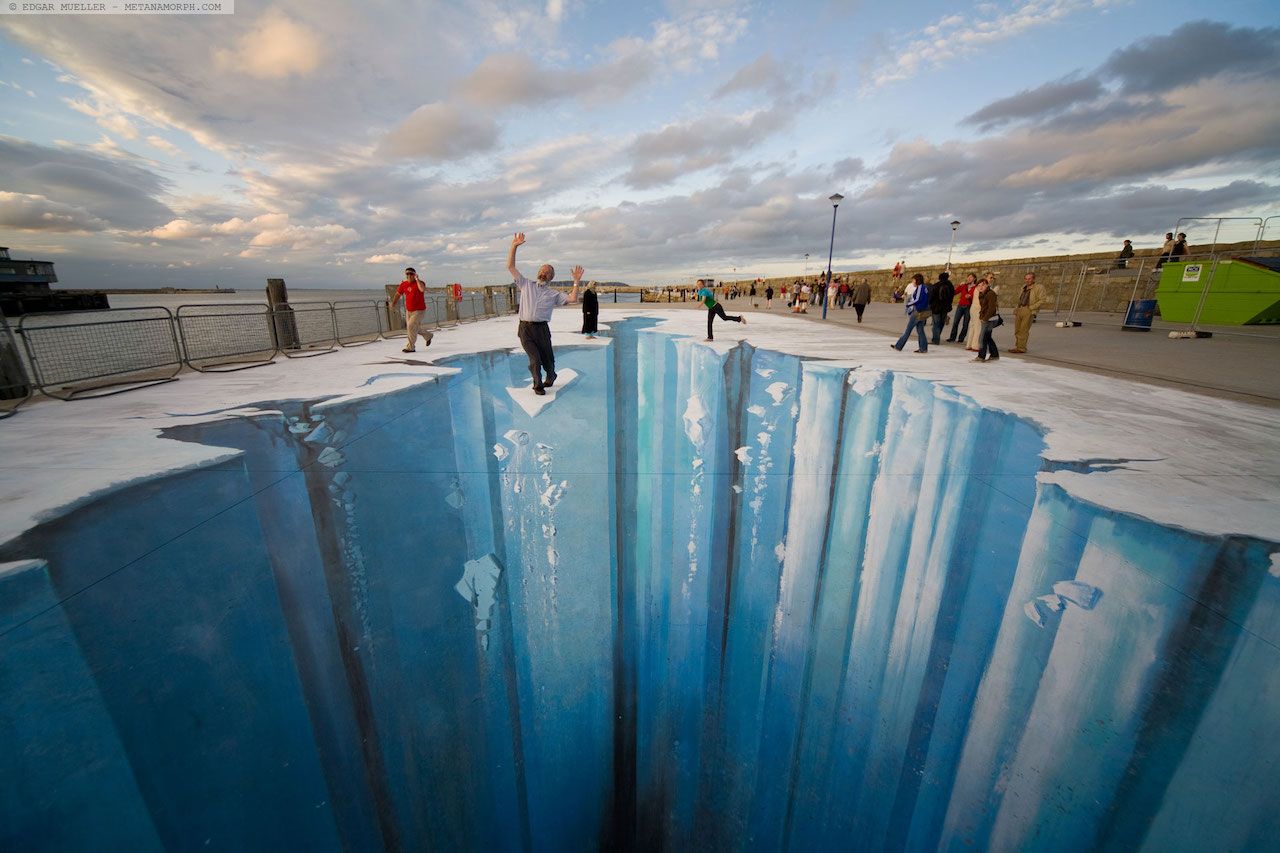
Have you ever seen those mind-bending optical illusion street art that turns a flat sidewalk into a deep dark abyss? From the right angle, it feels like you are standing on the edge of a cliff, staring into the gaping unknown. You might even ask a friend to hold the camera while you carefully step on the painted “debris” to strike a frightened pose for your Instagram.
This is the concept behind parallax mapping, shifting textures to trick your eyes into seeing real depth.
Getting Started
Why Tangent Space?
Before diving into this tutorial, let’s talk about the setup for this little project and why it is important that we work in tangent space.
Our height maps, normal maps, and UVs are defined in texture space, but light and view directions exist in world space. To make lighting interact correctly with texture-based surface detail, we transform those vectors into tangent space, a local space aligned with each fragment’s surface and UV layout.
Tangent space makes lighting calculations independent of the object’s rotation. Without it, the effect would look visually incorrect since shadows and highlights would stay fixed relative to world space instead of following the surface. Rotating the object would break the illusion, as lighting would no longer match the texture detail.
Setting Up Tangent Space in HLSL
To work in tangent space, we need to create a transformation matrix called the TBN matrix, composed of the tangent, bitangent, and normal vectors in world space.
Here’s how to compute this in the vertex shader:
1
2
3
4
5
6
7
8
9
10
11
12
13
14
15
16
17
18
19
20
21
22
23
24
25
26
27
v2f vert(appdata v)
{
    v2f o;

    // Transform the vertex position to clip space for rendering
    o.pos = UnityObjectToClipPos(v.vertex);

    // Convert the vertex position to world space (used for lighting/view direction)
    o.worldPos = mul(unity_ObjectToWorld, v.vertex).xyz;

    // Apply texture scaling and offset
    o.uv = TRANSFORM_TEX(v.uv, _MainTex);

    // Convert the vertex normal from object to world space
    half3 worldNormal = UnityObjectToWorldNormal(v.normal);

    // Convert the vertex tangent from object to world space
    half3 worldTangent = normalize(mul((float3x3)unity_ObjectToWorld, v.tangent));

    // Compute the bitangent using the cross product and handedness (v.tangent.w)
    float3 worldBitangent = normalize(cross(worldNormal, worldTangent) * v.tangent.w);

    // Construct the TBN matrix for transforming directions into tangent space
    o.TBN = float3x3(worldTangent, worldBitangent, worldNormal);

    return o;
}
In the fragment shader, we can then transform any world-space vector into tangent space using the TBN matrix:
1
2
3
4
5
6
7
8
9
10
11
12
13
14
15
16
fixed4 frag(v2f i) : SV_Target
{
    // Compute the view direction in world space (from fragment to camera)
    half3 v = normalize(_WorldSpaceCameraPos - i.worldPos);

    // Get the main directional light direction in world space
    half3 l = normalize(_WorldSpaceLightPos0.xyz);

    // Transform the view direction into tangent space using the TBN matrix
    half3 v_TS = normalize(mul(i.TBN, v));

    // Transform the light direction into tangent space using the TBN matrix
    half3 l_TS = normalize(mul(i.TBN, l));

    // Lighting and parallax code...
}
This ensures that our lighting and shadowing calculations align perfectly with the texture data no matter how the surface is oriented in the world.
How to use the code here in my shader?
Throughout this tutorial, we’ll be implementing the following parallax-related functions:
1
2
3
4
5
6
7
8
// Simple Parallax Mapping
float2 SimpleParallaxMapping(sampler2D depthMap, float2 texCoords, float3 viewDir, float depthScale);

// Steep Parallax Mapping + Parallax Occlusion Mapping
float2 SteepParallaxMapping(sampler2D depthMap, float2 texCoords, float3 viewDir, int numLayers, float depthScale);

// Self-Shadowing
float SelfShadowing(sampler2D depthMap, float2 texCoords, float3 lightDir, float numLayers, float depthScale);
Example Usage
Once you’ve transformed your view and light vectors into tangent space, you can plug them directly into the functions:
1
2
3
4
5
6
7
8
9
10
11
// If you want simple parallax mapping
float2 texCoords = SimpleParallaxMapping(_Depth, i.uv, viewDir_TS, _DepthScale);

// If you want steep parallax mapping + parallax occlusion mapping
float2 texCoords = SteepParallaxMapping(_Depth, i.uv, v_TS, _NumberOfLayers, _DepthScale);

// Using self-shadowing
float parallaxShadows = SelfShadowing(_Depth, texCoords, l_TS, _NumberOfLayers, _DepthScale);

// Lighting code...
return ambient + (diffuse + specular) * parallaxShadows;
Don’t worry if you run into any setup issues. You can use the shaders I wrote for this tutorial: Blinn-Phong, Cook-Torrance, and the complete Parallax Mapping shader. You can also check out the full repository here.
Shader Parameters – Blinn-Phong
| Property | Display Name | Description |
|---|---|---|
_DiffuseColour | Diffuse Colour | Defines the base colour of the material, used in diffuse lighting calculations. |
_MainTex | Albedo (RGB) | The main texture applied to the surface, representing its base colour (albedo). |
_Normal | Normal Map | The normal map used to simulate fine surface detail and lighting variation. |
_NormalStrength | Normal Strength | Scales the influence of the normal map, exaggerating or softening surface bumps. |
_Depth | Depth Map | The inverse of a height map used for parallax mapping to simulate surface depth. |
_NumberOfLayers | Number of Layers | Controls how many steps are taken in the raymarch for parallax and shadow tracing. |
_DepthScale | Depth Scale | Adjusts how strong the parallax displacement effect appears. |
_UseSteep | Steep Parallax | Enables steep parallax mapping for more accurate depth simulation using raymarching. |
_UseShadows | Enable Shadows | Enables self-shadowing by checking whether light is occluded by surface features. |
_TrimEdges | Trim Edges | Discards pixels with distorted or invalid UVs to avoid edge artefacts from parallax. |
_SpecularExponent | Specular Exponent | Controls the sharpness of specular highlights — higher values give tighter reflections. |
_k | Coefficients (Ambient, Diffuse, Specular) | A vector defining the strength of ambient, diffuse, and specular light contributions. |
Shader Parameters – Cook-Torrance
| Property | Display Name | Description |
|---|---|---|
_DiffuseColour | Diffuse Colour | Defines the base colour of the material, used in diffuse lighting calculations. |
_MainTex | Albedo (RGB) | The primary texture applied to the surface, representing the material's albedo or colour map. |
_Roughness | Roughness Map | Greyscale texture map that defines the micro-roughness of the surface. |
_sigma | Roughness Factor | Roughness factor used to globally scale or adjust the effect of the roughness map. |
_Normal | Normal Map | The normal map texture that adds per-pixel detail for realistic light interaction. |
_NormalStrength | Normal Strength | Controls the strength of the normal map effect, exaggerating or softening surface details. |
_Depth | Depth Map | The inverse of a height map used for parallax mapping to simulate surface depth. |
_NumberOfLayers | Number of Layers | The number of layers used for parallax raymarching. Higher values increase accuracy at the cost of performance. |
_DepthScale | Depth Scale | Controls the depth intensity of the parallax effect. Lower values produce subtle displacement; higher values exaggerate it. |
_UseSteep | Steep Parallax | Enables Steep Parallax Mapping for more accurate depth simulation via raymarching. |
_UseShadows | Enable Shadows | Enables self-shadowing by tracing whether light is occluded by displaced surface geometry. |
_TrimEdges | Trim Edges | Discards fragments with distorted or out-of-bounds UVs near texture edges, preventing artefacts. |
_Metallic | Metallic | Controls the metallic quality of the surface. 0 = dielectric (non-metal), 1 = pure metal. |
_RefractiveIndex | Refractive Index | Defines the refractive index used in the Fresnel calculation. Affects how reflective the surface appears at grazing angles. |
Simple Parallax Mapping
At its core, parallax mapping distorts parts of a 2D texture based on how we view the surface. Are we looking straight down at it, or viewing it from an angle? This is called the view angle. Another crucial element is determining how much different parts of the texture should shift. This information comes from the depth map, which is essentially the inverse of the height map.
With this information, we can now compute the displaced texture coordinates for each pixel rendered on the screen.
Firstly, we must retrieve the depth value for the current pixel we are computing for. This can be simply done by sampling the depth map with the interpolated UVs for the current pixel.
1
2
3
4
float2 ParallaxMapping(sampler2D depthMap, float2 texCoords, float3 viewDir, float depthScale)
{
  float depth = tex2D(depthMap, texCoords).r;
}
The depth values and depth maps we talk about here are not to be confused with the depth values and depth maps associated with the depth buffer!
We can now calculate the shift in the form of a vector \(p\), which depends on the viewing angle and the depth value. The key idea is to increase the shift when viewing the surface at an angle, and reduce it when looking straight down. To understand this better, let’s analyse how \(viewDir\) behaves.
From the visualisation, we can observe the following properties:
- \(viewDir_z\) approaches 1 when looking directly down at the surface.
- \(viewDir_z\) approaches 0 when looking at an angle (approaching parallel to the surface).
- Conversely, \(viewDir_y\) increases as we tilt towards a horizontal view and decreases as we look downward.
- For simplicity, in this visualisation, we are only considering the \(yz\) plane, so \(viewDir_x\) is omitted.
This means that \(viewDir_z\) effectively acts as a depth factor, determining how much perspective distortion occurs. When looking straight down, there should be minimal distortion, and when looking at an angle, the shift should be more pronounced.
A natural way to achieve this effect is to project the 3D view direction onto the 2D texture space by dividing the \(xy\) components of \(viewDir\) by its \(z\) component:
\[p = \frac{viewDir_xy}{viewDir_z} * (\text{depth} * \text{depth scale factor})\]This division ensures that:
- \(\frac{viewDir_xy}{viewDir_z}\) is small when \(viewDir_z\) is large (looking directly down at the surface).
- \(\frac{viewDir_xy}{viewDir_z}\) is large when \(viewDir_z\) is small (looking at the surface at an angle).
The displacement is then scaled appropriately based on the pixel’s depth value, \(\text{depth}\), and a user-defined depth scale factor, \(\text{depth scale factor}\), ensuring a flexible and controllable parallax effect.
Finally, we compute the new texture coordinates, \(t'\), by adjusting the texture coordinates, \(t\):
\[t' = t - p\]This shifts the texture sample position, creating the illusion of depth by making closer regions appear to move more than distant ones.
Here is the implementation of this concept in code:
1
2
3
4
5
6
float2 ParallaxMapping(sampler2D depthMap, float2 texCoords, float3 viewDir, float depthScale)
{
    float depth = tex2D(depthMap, texCoords).r;
    float2 p = viewDir.xy / viewDir.z * depth * depthScale;
    return texCoords - p;
}
Here is a visualisation of the approach that I have prepared to ease your understanding. The red ball is the new texel (texture element) that the viewer sees after computing the parallax shift. Notice how the vector \(p\) (length of the red line) changes as we vary the viewing angle.
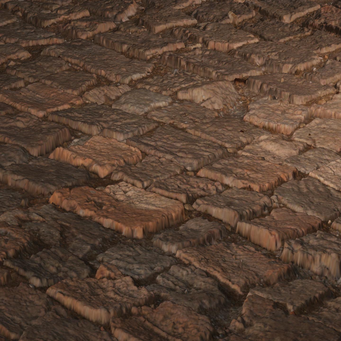
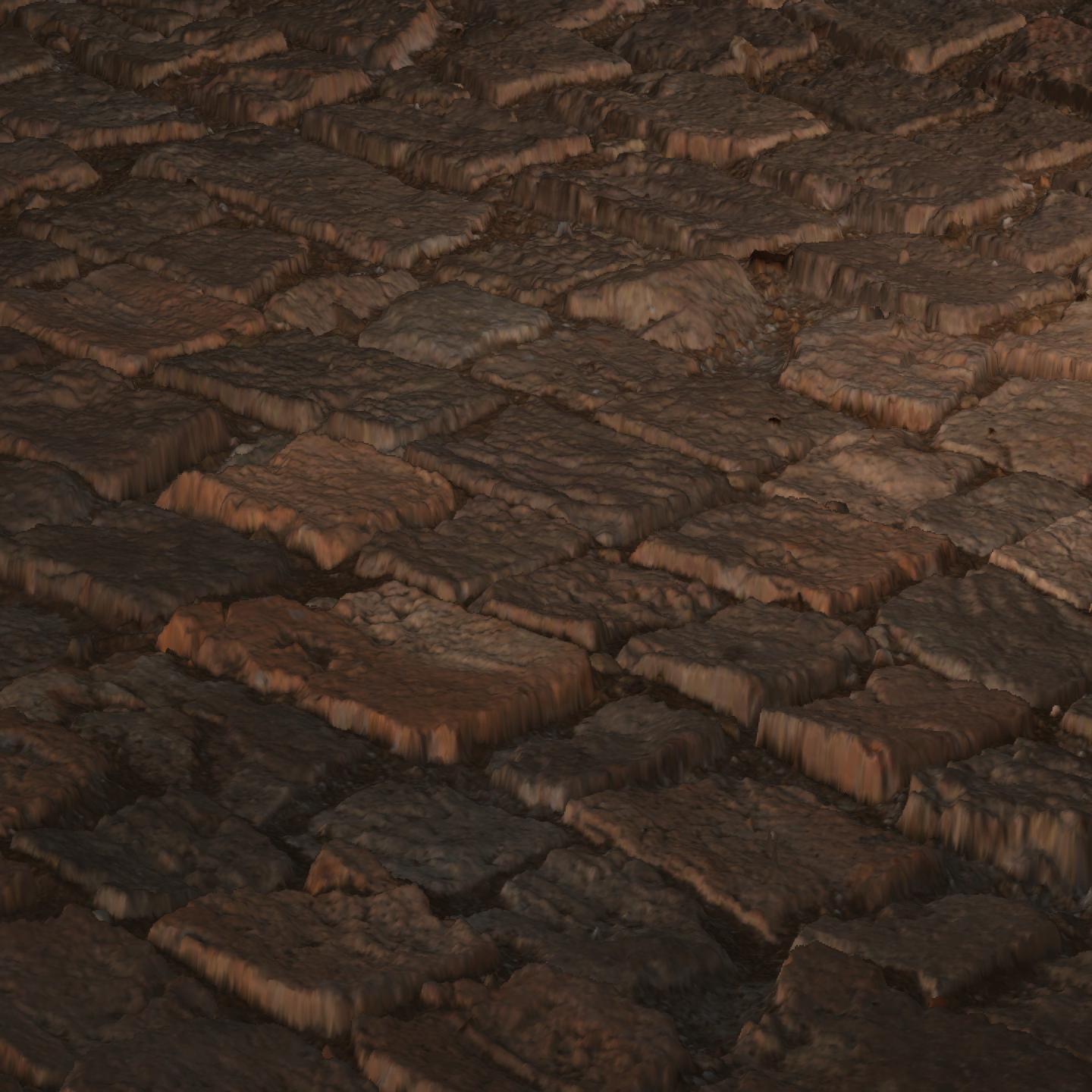
Below are the results of this implementation in two different lighting models, Blinn-Phong and Cook-Torrance + Oren-Nayar.
Expand to view the images
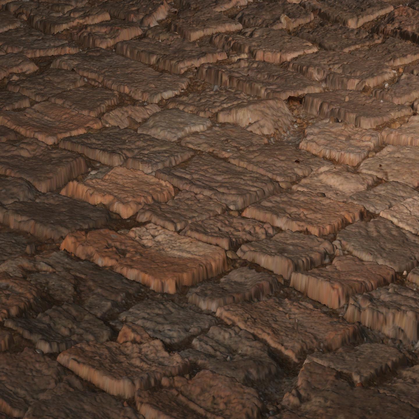
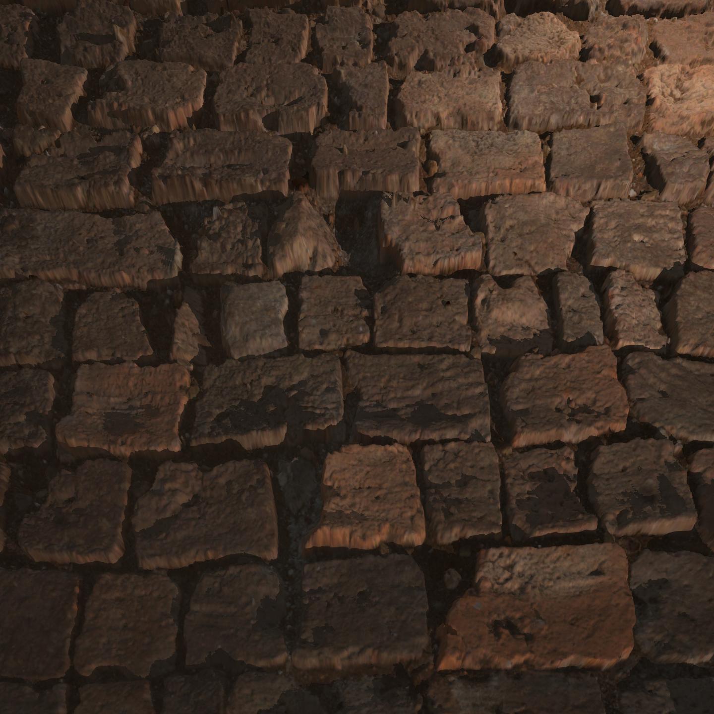
| Blinn-Phong (Empirical) | Cook-Torrance (Physical) |
|---|---|
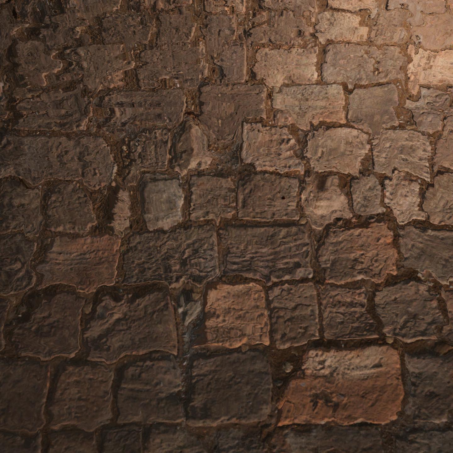 | 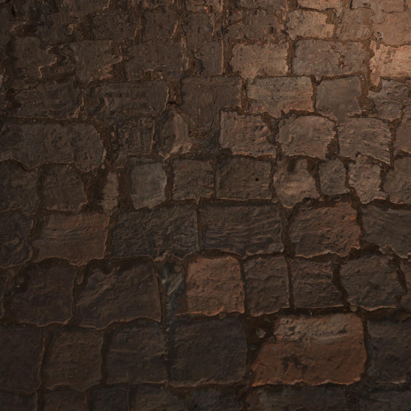 |
 |  |
As you can see the results look decent when looking down at the surface. However, as you might have expected, this basic computation does not come without its drawbacks. When looking at an angle, the algorithm fails to uphold a realistic parallax shift, creating this rather distorted and warped effect on the plane.
This happens because our simple parallax mapping only shifts the texture coordinates without actually considering how different parts of the surface should block or hide others. In reality, when looking at a rough surface from an angle, some areas should be hidden behind taller parts, while others should be more exposed.
To solve this, we need to look into a more robust approach: Steep Parallax Mapping.
Steep Parallax Mapping
To address the issue from before and to create a more convincing effect, we need a way to simulate depth more accurately — something that allows us to refine how the surface appears as we look around. Instead of applying a single offset, what if we could trace along the surface in steps, gradually refining the displacement?
Imagine walking through your room in the dark, trying to avoid bumping into furniture. If you take big steps, you risk misjudging their exact location, possibly stumbling into them, hurting yourself, and waking your parents up. But by taking small, careful steps, you can feel your way around and accurately determine where everything is.
Similarly, Steep Parallax Mapping doesn’t just make one big guess. Instead, it takes multiple smaller steps, gradually refining the depth adjustment to create a much more realistic effect.
Going into more detail, we divide the total depth range (0 to 1) into multiple layers, allowing us to traverse the depth map in smaller, incremental steps. Starting from the viewer’s eye, we step along the view direction (\(viewDir\)) after hitting the surface at point A.
We step into each layer in a fixed stepVector, and at every step, we compare the sampled depth value from the depth map (currentDepthMapValue) with the current layer depth (currentLayerDepth). If the sampled depth is still greater than the current layer depth, we continue stepping forward until the currentDepthMapValue is smaller than the currentLayerDepth.
Before we address any questions, let me show you how this can be implemented:
1
2
3
4
5
6
7
8
9
10
11
12
13
14
15
16
17
18
19
20
21
22
23
24
25
26
27
28
29
30
31
float2 SteepParallaxMapping(sampler2D depthMap, float2 texCoords, float3 viewDir, int numLayers, float depthScale)
{
    // Calculate the size of a single layer
    float layerDepth = 1.0 / numLayers;

    // Determine the step vector based on our view angle
    float2 p = viewDir.xy * depthScale;
    float2 stepVector = p / numLayers;

    // Initialise and set starting values before the loop
    float currentLayerDepth = 0.0;
    float2 currentTexCoords = texCoords;

    // Sample with fixed LOD to avoid issues in loops that will cause GPU timeouts
    float currentDepthMapValue = tex2Dlod(depthMap, float4(currentTexCoords, 0, 0.0)).r;

    // Loop until we have stepped too far below the surface (the surface is where the depth map says it is)
    while (currentLayerDepth < currentDepthMapValue)
    {
        // Shift the texture coordinates in the direction of step vector
        currentTexCoords -= stepVector;

        // Sample the depthmap with the new texture coordinate to get the new depth value
        currentDepthMapValue = tex2Dlod(depthMap, float4(currentTexCoords, 0, 0.0)).r;

        // Move on to the next layer
        currentLayerDepth += layerDepth;
    }

    return currentTexCoords;
}
Why does this work? What does it mean to check if the currentLayerDepth is bigger than the currentDepthMapValue? The explanation is simpler than you think.
Imagine you’re entering a pool in the dark and you want to find the water level. You lower yourself gradually, step by step down the staircase. At each step, you feel if your feet are still in the air or have touched the water. Suddenly in one step, your entire leg is submerged into the water! Here you can conclude for the sake of simplicity that the water level is at the previous step. Don’t worry, we will explore a smarter approach later.
Now let’s analyse the code.
1. Divide the depth map into multiple layers
1
float layerDepth = 1.0 / numLayers;
We split the total depth range that starts from 0 (top) to 1 (bottom) into evenly spaced layers. Each layer is like a step on the staircase in our pool analogy earlier.
2. Calculate the step vector
1
2
float2 p = viewDir.xy * depthScale;
float2 stepVector = p / numLayers;
Here, we’re figuring out how to shift the texture coordinates in the direction we’re looking.
viewDir.xygives us the viewing angle across the surface.depthScalecontrols how exaggerated the depth effect is.pgives us the total shift in texture coordinates we’ll distribute across the layersstepVectoris the direction in which we step (and also how far) for each layer. Basically determining how large a step in the staircase is in our pool analogy.
3. Initialise Values
1
2
3
float currentLayerDepth = 0.0;
float2 currentTexCoords = texCoords;
float currentDepthMapValue = tex2Dlod(depthMap, float4(currentTexCoords, 0, 0.0)).r;
We’re just setting our initial values before here we enter the loop.
float4 tex2Dlod(sampler2D samp, float4 texcoord) is used to specify a level of detail (LOD) for texture sampling, so the GPU doesn’t have to figure it out on its own — this helps prevent GPU timeouts.
The LOD is included in the float4 texcoord parameter, written like this: float4(uv.x, uv.y, 0, lod). LOD values start at 0 (full detail), and higher values (1, 2, 3, …) use lower-resolution mipmap levels.
4. Step through the layers
1
2
3
4
5
6
7
8
while (currentLayerDepth < currentDepthMapValue)
{
    currentTexCoords -= stepVector;
    currentDepthMapValue = tex2Dlod(depthMap, float4(currentTexCoords, 0, 0.0)).r;
    currentLayerDepth += layerDepth;
}

return currentTexCoords;
We keep marching through the surface layer by layer until we go too deep. Here’s what happens at each step:
Check if we’re still above the surface. If our current layer depth is less than the depth from the depth map, it means the surface lies deeper than our current position — in other words, we haven’t reached it yet. So we continue stepping forward.
If we’ve gone too deep, we stop. At this point, we return the last texture coordinates where we were still above the surface. This gives us the illusion of correct surface depth.
Otherwise, we keep stepping:
- Update
currentTexCoordsby taking the next one in the direction of thestepVector. - Sample the depth map at the new texture coordinates.
- Proceed to the next layer.
- Update
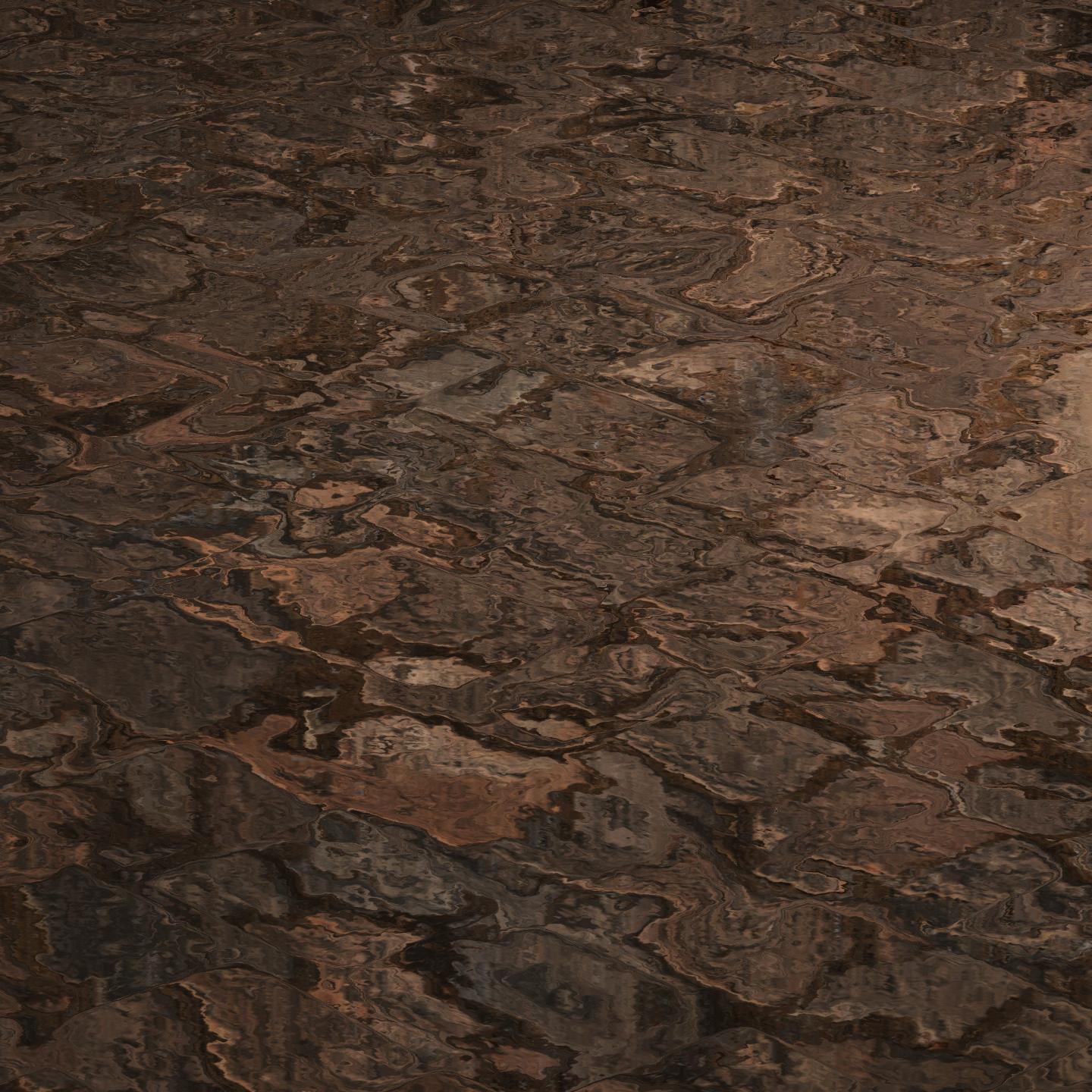
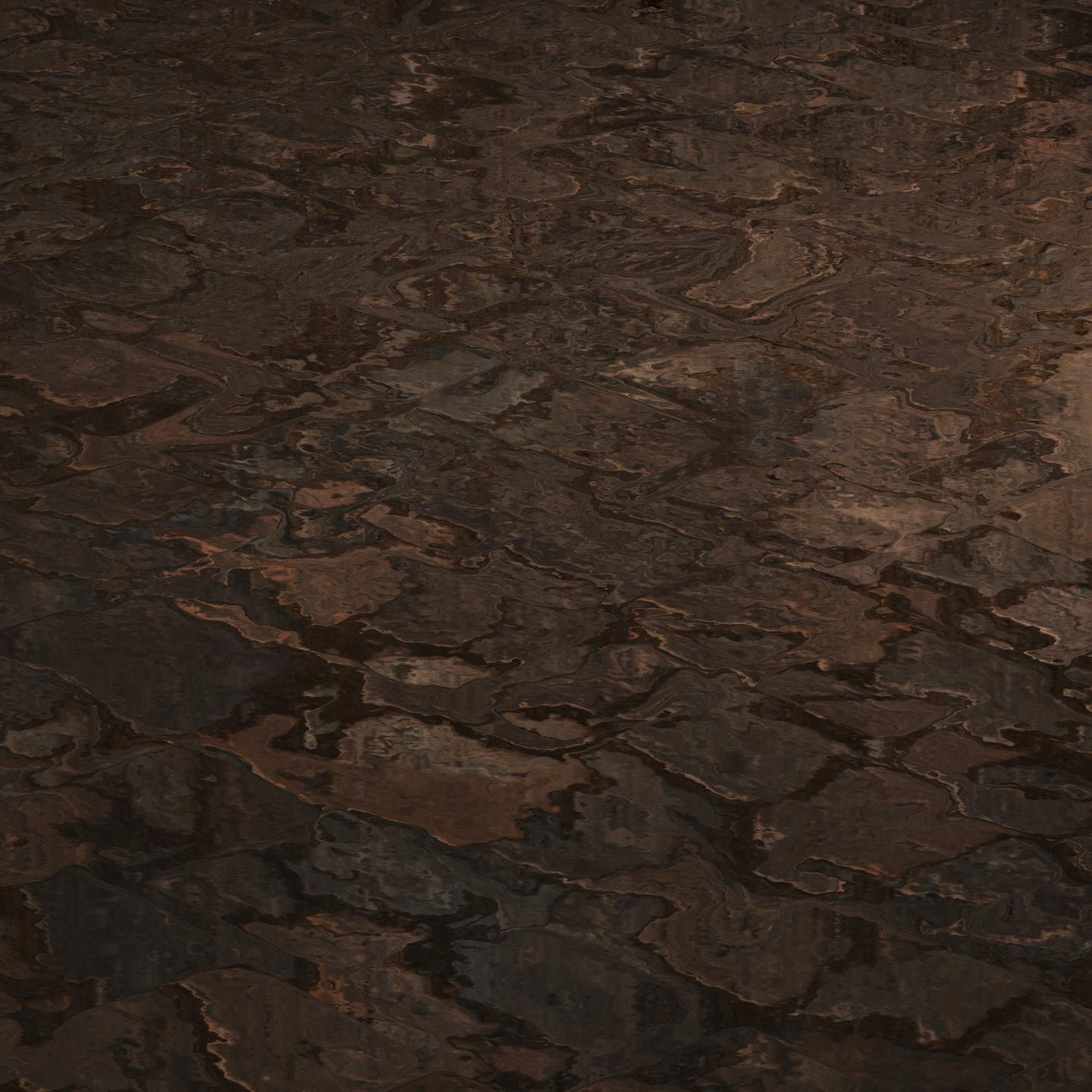
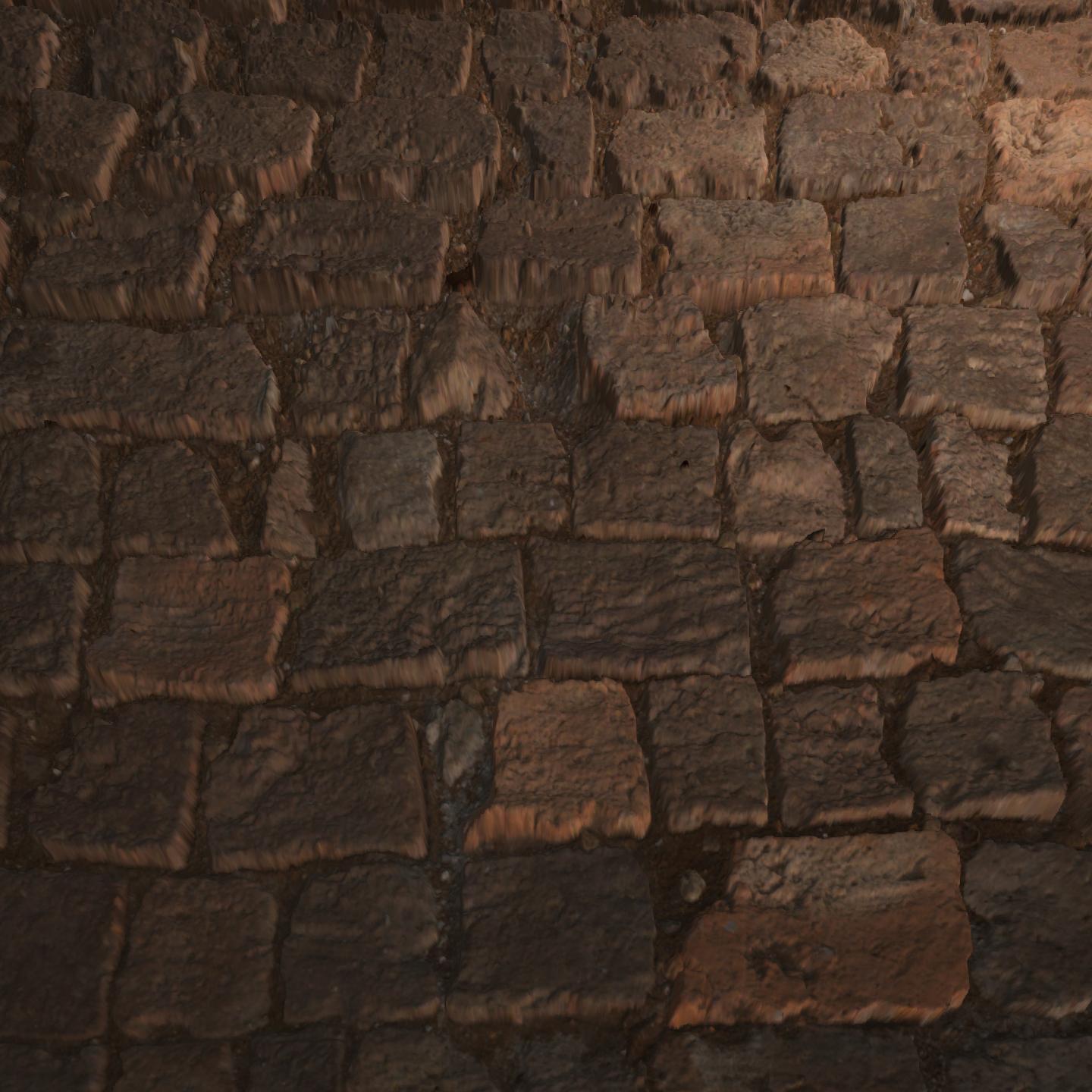
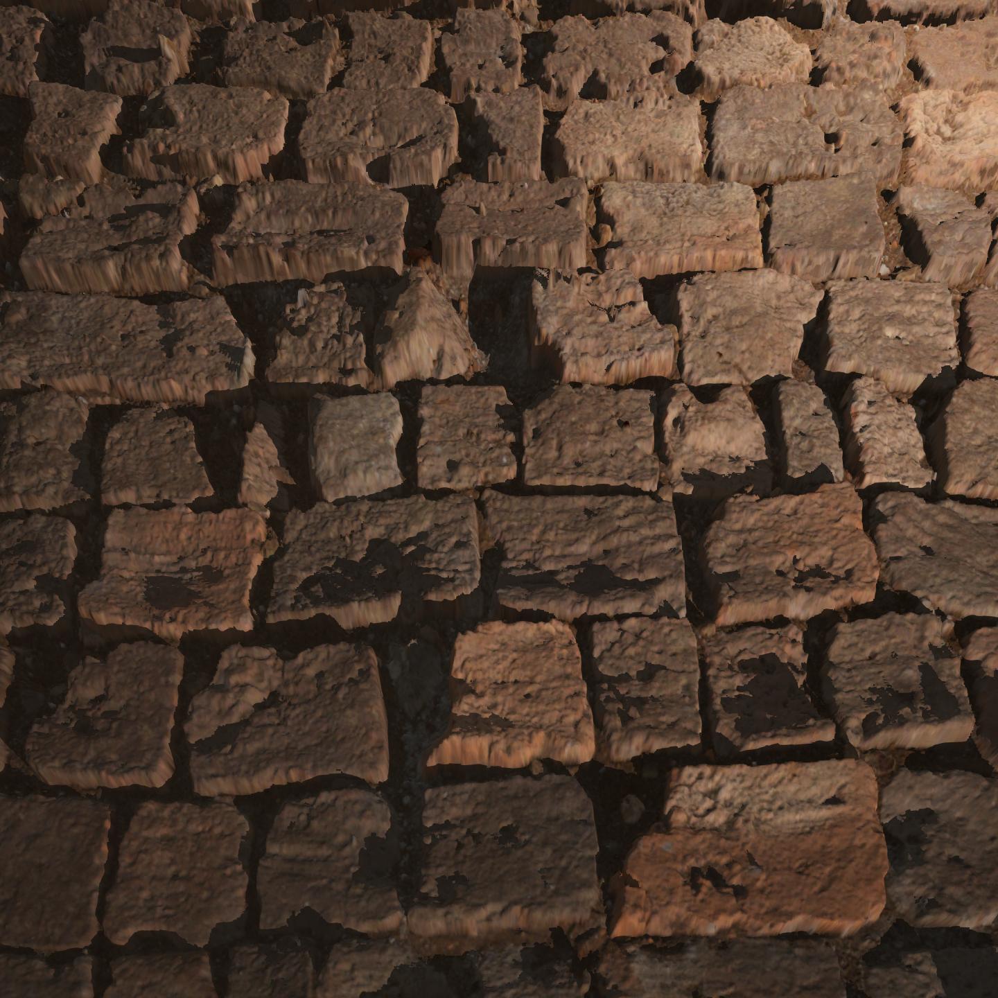
Finally, here are the results of our new approach.
Expand to view the images
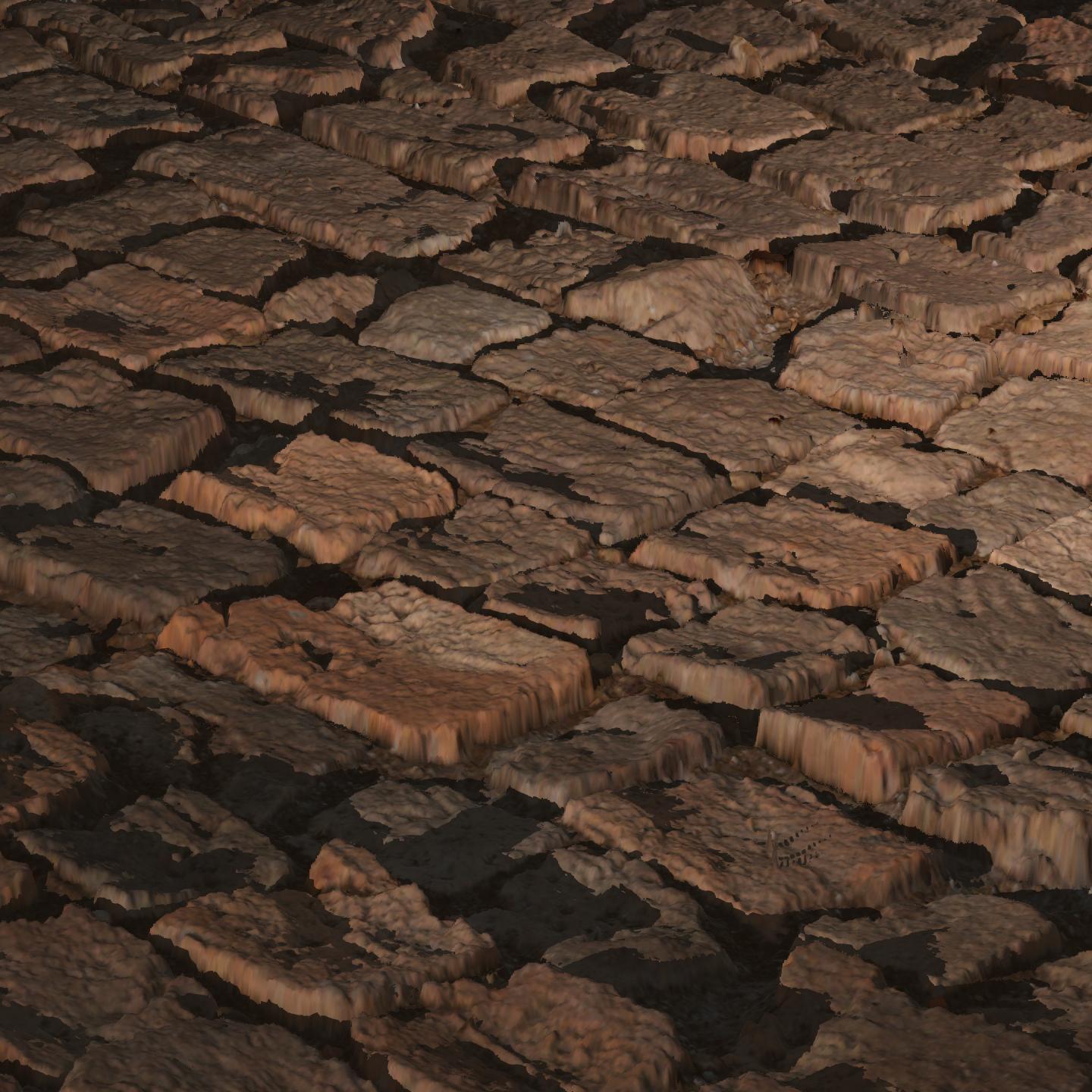
| Blinn-Phong (Empirical) | Cook-Torrance (Physical) |
|---|---|
 |  |
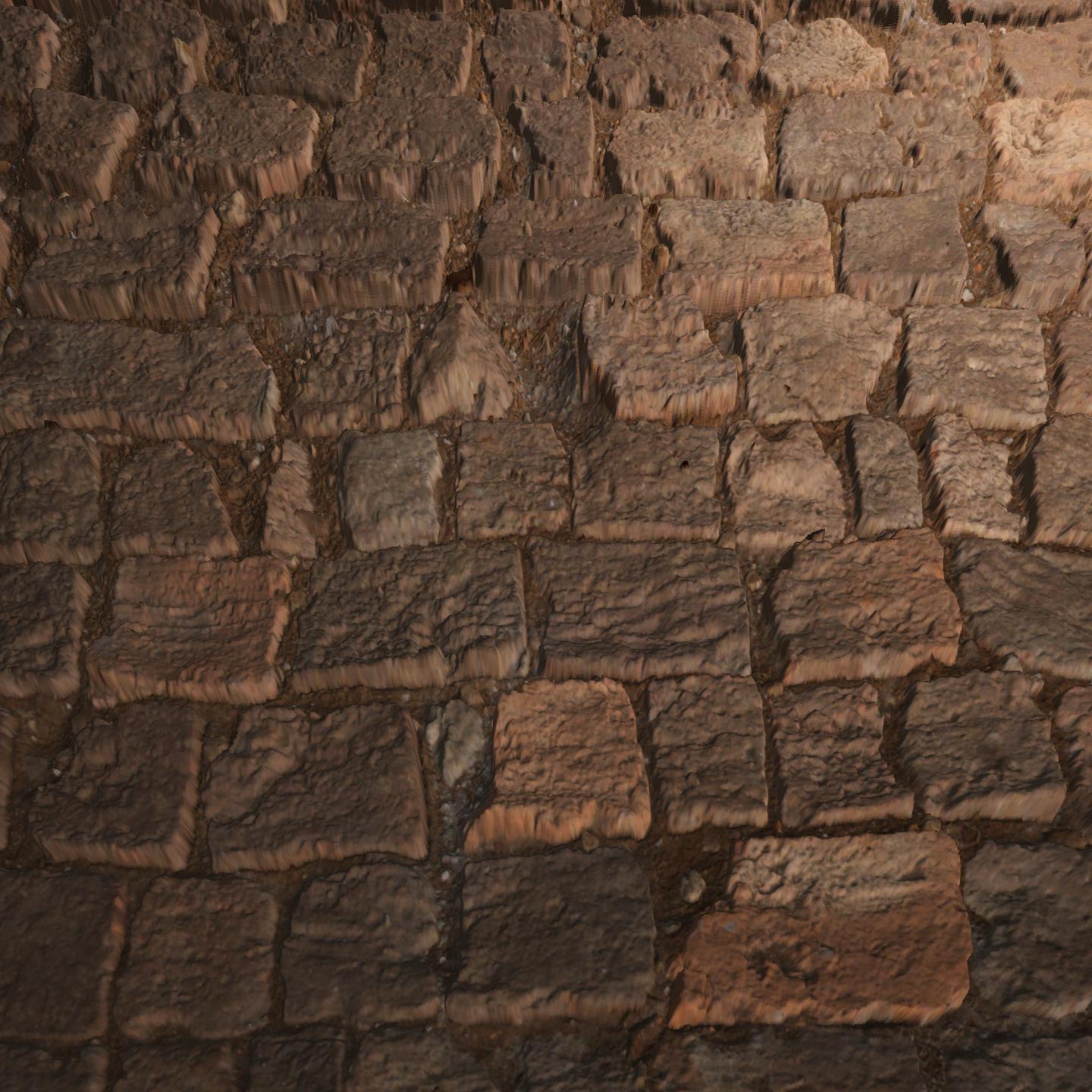 |  |
This is a huge improvement over the basic version. However, even with a high layer count (256 in this example), you can still notice visible steps or banding between layers. The illusion breaks down slightly because we’re still only returning the texture coordinates from the last step before we went too deep, without considering where the actual surface lies between the last two steps.
And beyond visual quality, we also want to minimise the layer count for performance reasons especially in real-time applications like games.
Parallax Occlusion Mapping
To address both issues that we face in Steep Parallax Mapping, we can take a smarter approach: instead of just stopping at the last valid step, we can interpolate between the two most recent samples to more accurately estimate where the surface was intersected.
This is the key idea behind Parallax Occlusion Mapping, a refinement of Steep Parallax Mapping that adds this extra step for improved precision and smoother results.
The maths behind it is actually quite simple.
We identify two key moments:
The last step where we were still above the surface
The first step where we ended up below it
At each of these points, we calculate how far we are from the surface. By comparing those offsets, we can estimate how far along that transition the surface was actually crossed.
Thinking of this as,
“We’re moving from
surfaceOffsetBefore(above the surface) tosurfaceOffsetAfter(below the surface). At what fraction along that path did we hit the surface?”
the formula becomes:
\[\text{weight} = \frac{\text{surfaceOffsetAfter}}{\text{surfaceOffsetAfter} + \text{surfaceOffsetBefore}}\]Since because surfaceOffsetBefore is always negative, we must flip the positive sign to a negative.
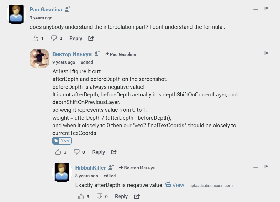
So we compute:
1
weight = surfaceOffsetAfter / (surfaceOffsetAfter - surfaceOffsetBefore);
This gives us a value between 0 and 1, telling us how far between the two texture coordinates the surface lies. We can then use that weight to blend between the texture coordinates from both steps.
Using this, our refined version of the algorithm looks like this:
1
2
3
4
5
6
7
8
9
10
11
12
13
14
// Compute the texture coordinates from the previous iteration
float2 prevTexCoords = currentTexCoords + stepVector;

// Compute how far below the surface we are at the current step
float surfaceOffsetAfter = currentDepthMapValue - currentLayerDepth;

// Compute how far above the surface we were at the previous step
float surfaceOffsetBefore = tex2Dlod(depthMap, float4(prevTexCoords, 0, 0)).r - currentLayerDepth + layerDepth;

// Linearly interpolate the texture coordinates using the calculated weight
float weight = surfaceOffsetAfter / (surfaceOffsetAfter - surfaceOffsetBefore);
float2 finalTexCoords = prevTexCoords * weight + currentTexCoords * (1.0 - weight);

return finalTexCoords;
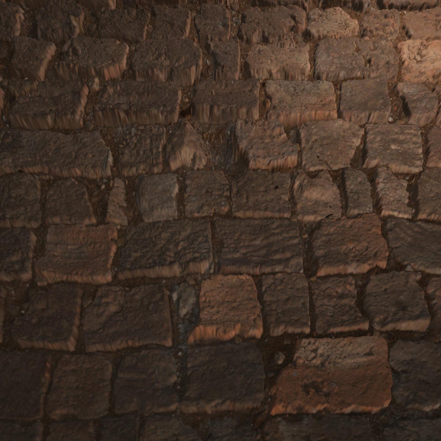
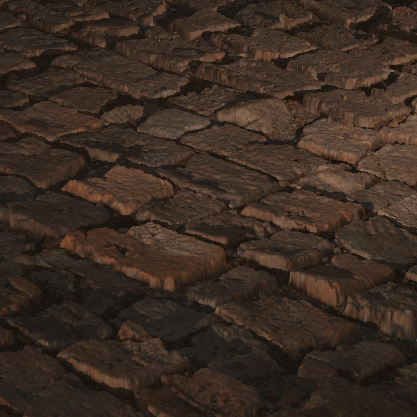
And here are the results without the artefacts from before with the same layer count:
Expand to view the images
| Blinn-Phong (Empirical) | Cook-Torrance (Physical) |
|---|---|
 |  |
 |  |
Self-Shadowing
We have achieved what we sought to achieve: a relatively low-cost approach in enhancing realism by faking depth on a flat surface.
Why don’t we take it a step further?
If you set up your scene with lights, you will notice that even with convincing surface detail, the illusion breaks down when lighting interacts with the surface. If light hits a deep groove or crack, we expect parts of it to be in shadow, yet everything looks uniformly lit and flat.
To make our illusion even more convincing, we need to simulate this interaction between light and surface detail.
This is where self-shadowing comes into play.
Understanding the Light Vector In Tangent Space
Before we can simulate self-shadowing, it’s important to understand how light vectors behave in this tangent space.
How does the light vector behave in tangent space?
In tangent space, the surface is aligned like this:
\(+x\): tangent (\(u\) direction)
\(+y\): bitangent (\(v\) direction)
\(+z\): surface normal, pointing outward
So a light shining from in front of the surface will point toward \(−z\) in tangent space. This is why the \(z\) component of the light vector becomes so important for self-shadowing.
What can we do with this information?
Now that we know how to interpret light direction in tangent space, we can use the \(z\) component to decide whether self-shadowing should be calculated at all.
If lightDir.z >= 0, the light is behind the surface, and no surface detail should cast shadows in this case. To avoid unnecessary computation, we simply skip the shadowing pass:
1
if (lightDir.z >= 0.0) return 0.0;
This keeps the shader efficient and ensures that shadow rays are only traced when the surface is lit from the front where shadowing is visually meaningful.
Self-Shadowing Algorithm
Once we’ve confirmed that the light is in front of the surface (lightDir.z < 0.0), we can proceed with simulating how light rays interact with the surface detail described by the height map. The idea is to march along the light’s direction in tangent space, checking if any elevated point along the path blocks the light.
First, we calculate the number of layers and the step size per layer:
1
2
3
float layerDepth = 1.0 / numLayers;
float2 p = lightDir.xy / lightDir.z * depthScale;
float2 stepVector = p / numLayers;
Here, p is the total projected UV offset in the direction of the light, scaled by depthScale. Dividing by numLayers gives us the UV step for each iteration.
We then begin ray marching from the current texture coordinates (calculated from Parallax Mapping) and initial depth:
1
2
3
float2 currentTexCoords = texCoords;
float currentDepthMapValue = tex2D(depthMap, currentTexCoords).r;
float currentLayerDepth = currentDepthMapValue;
To avoid false shadowing from very small height changes, we introduce a small bias:
1
float shadowBias = 0.03;
This is an aesthetic choice that helps avoid noisy shadows caused by small bumps in the surface. We also limit the number of iterations to keep the shader efficient and compatible with GPU loop unrolling limits:
1
2
int maxIterations = 32;
int iterationCount = 0;
Now we walk layer by layer along the light direction, this time traversing upwards instead of downwards like we did before:
1
2
3
4
5
6
7
while (currentLayerDepth <= currentDepthMapValue + shadowBias && currentLayerDepth > 0.0 && iterationCount < maxIterations)
{
    currentTexCoords += stepVector;
    currentDepthMapValue = tex2D(depthMap, currentTexCoords).r;
    currentLayerDepth -= layerDepth;
    iterationCount++;
}
This loop ends if the ray exits the surface, hits an occluder, or exceeds the iteration limit.
Finally, we determine if the light path is blocked:
1
return currentLayerDepth > currentDepthMapValue ? 0.0 : 1.0;
If the ray reaches a point where the value stored in the depth map at the current texture coordinate is below the current layer depth, it means something blocks the light, the fragment is in shadow (0.0). If the ray completes without hitting such a point, the fragment is fully lit (1.0).
Here are the final results for this tutorial:
Expand to view the images
| Blinn-Phong (Empirical) | Cook-Torrance (Physical) |
|---|---|
 |  |
 |  |
Afterword
Thank you so much for reading, especially if you made it all the way to the end.
Parallax mapping was one of the more confusing topics for me when I first started learning shaders. At first glance, it felt complex and maths-heavy, but once I understood the core idea, I realised it’s actually a very simple and elegant trick.
I truly hope this post helped you see it the same way and more importantly, helped you understand how and why it works. If you followed along and learned something new, that means a lot to me.
Feel free to use and modify the shaders provided. And if you build something cool with them, I’d love to see it!
Credits
- Joey de Vries, for his excellent tutorial on LearnOpenGL. The core algorithm and structure used in this post are based on his original GLSL implementation, adapted here for HLSL.
- Rabbid76, for their detailed answer on StackOverflow, which helped guide the self-shadowing implementation.